Pironman 5 NAS HAT
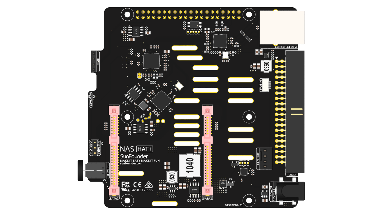
Power Input
The board uses a DC 5.5-2.1 input connector, with an input voltage requirement of 12V/4A. The power input supplies power directly to the hard drives, so the voltage must be 12V ±10%.
PCIe Input and PCIe Switch
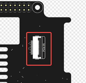
The PCIe connector is located on the back of the board and uses a standard Raspberry Pi PCIe FFC interface to connect to the Raspberry Pi 5. The PCIe interface is split into two PCIe Gen2 lanes via an onboard ASM1182e PCIe switch, which connects to the 2.5G Ethernet controller and the SATA controller. Note: ASM1182e supports PCIe Gen2 input/output only and does not support Gen3.
2.5G Ethernet Controller
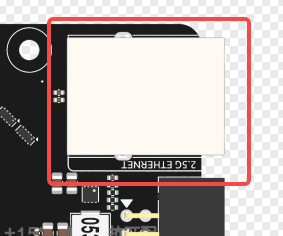
The board integrates a PCIe to 2.5G Ethernet controller, routed through the PCIe switch.
This interface can be used in parallel with the onboard 1Gb Ethernet port on the Raspberry Pi.
The Ethernet controller uses the RTL8125 chip, compatible with the r8169 driver.
Most Linux kernels include this driver by default, so no additional installation is typically required.
Dual SATA Ports
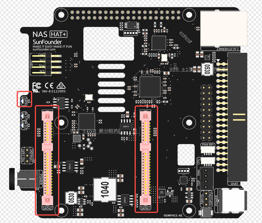
The board uses an ASM1061 PCIe to dual SATA controller, allowing connection of 3.5” or 2.5” SATA hard drives.
RAID0/RAID1 can be configured via the mdadm software tool.
A single SATA LED indicates disk activity; it will blink when either drive is accessed.
Raspberry Pi GPIO Header
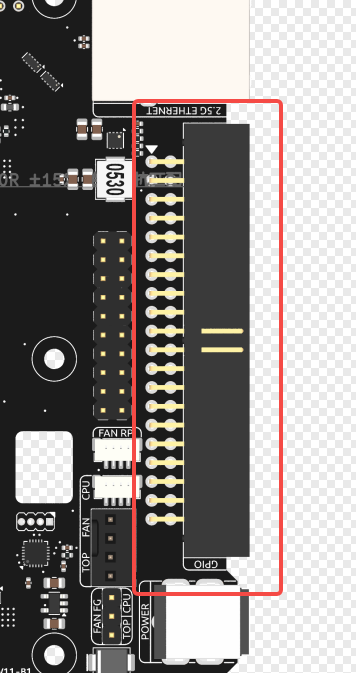
The board replicates the full Raspberry Pi GPIO header. Except for the I2C interface (used for the OLED display) and the ID SC/ID SD pins (connected to the onboard EEPROM), all GPIO pins are fully available. Since I2C allows multiple devices on the same bus, these pins are also accessible externally.
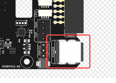
Fan Interface
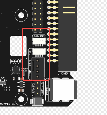
The fan header adapts the Raspberry Pi’s 5V SH1.0 fan interface to a standard 12V PC case fan connector.
The FAN RPi port connects to the Raspberry Pi, while the TOP FAN port connects to the biggest fan on the case, and the CPU port connects to the activate cooler.
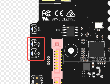
Fan Frequency Generator
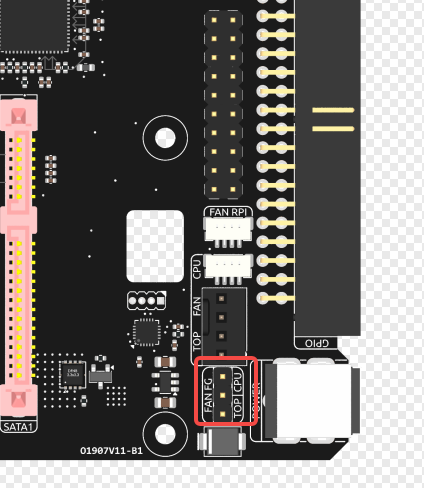
The Raspberry Pi has a Fan Frequency Generator interface that outputs a pulse signal proportional to the fan speed. The main control system reads the frequency of this pulse to calculate the real-time fan speed and determine whether the fan is running or experiencing any issues. You can switch jumpers to control either the top fan or the active cooler.
Power Button and Power Control
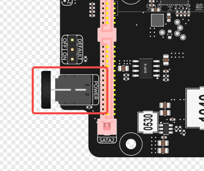
The power button includes an integrated power indicator LED. The button connects to an onboard microcontroller that manages the power switch logic:
Short press: Power on
Long press (2 seconds): Graceful shutdown (simulates pressing the Pi’s power button)
Hold for 5 seconds: Immediate power cut-off
Shutdown Behavior:
When a 2-second long press is detected, the microcontroller simulates a power button press on the Raspberry Pi via pogo pins.
It then monitors the 3.3V line to confirm system shutdown.
To enable this, make sure the Raspberry Pi EEPROM is configured with POWER_OFF_ON_HALT=1.
Once 3.3V drops, the microcontroller will cut off the main system power.
Even when the system is off, the microcontroller remains powered (~60mW consumption).
OLED Wake Feature: After powering on, a short press on the power button can wake the OLED from sleep mode.
OLED Interface
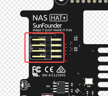
A 4-pin 2.54mm header is provided for an OLED module over the I2C bus. The board is designed to be compatible with a dedicated OLED display that can be directly mounted.
Default ON/OFF Jumper
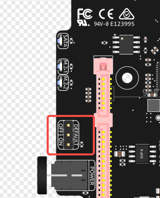
Default power behavior can be configured via a jumper:
Jumper on ON side: Auto power-on when power is applied
Jumper on OFF side: Requires pressing the power button to turn on
NVMe State
To indicate the state of the NVMe drive.